Week 1/2
For the production of this project, I utilised a range of different software which would handle specific throughout the making of the character.

I began by sculpting the base mesh of my character Zbrush which is the industry standard for SubD modelling within the VFX and Games industry. I began the sculpt with two spheres, one for the body and the other for the head. Using a series of brushes and manipulators within the application i was able to render a satisfactory anatomy study which would serve as the base of my character. manually sculpting the base mesh took me about a week from start to finish. However, this was just a sculpt. The model now needed to be evaluated from a technical perspective rather than an artistic one.
Zbrush being a very specialised tool was able tolerate high poly meshes pushing well beyond a 100 million. However this kind of magnitude would virtually kill any application further down the pipeline, therefore the model needed to be optimised for the next stages.
These stages consisted of retopology and UV mapping. The retopology stage is a redo of the topology which is essentially the flow of edge loops and normals. This is vital at ensuring the model can later be rigged/animated on further down the pipeline as well as have adequate UVs for texturing. However, the finished base mesh was at least 100 million. I could lower the SubD (resolution) level of the mode, however, this would lose a lot of the tertiary and secondary forms which would be vital in assuring a successful retopo.

Zbrush features a “decimation” tool which decreases the poly count considerably, however retains details where possible. This tool allows for the mesh to be exported at a relatively low poly count and would serve as a guide for retopology. The Decimation tool doesn’t serve any use beyond this as it compromises the topology.
I then imported the decimated base mesh into Maya which is where i would retopo the mesh. I could have done this in Zbrush with Zremesher which automatically does the topology however, the tool is not advised for use of deforming objects which is anything that would be animated on as the edge loop flow wouldn’t appropriate for the workflow. Even though I wasn’t going to animate the character, I did aim to pose it. therefore having correct topology would be important for this workflow. Furthermore, zremesher also keeps all the normals of equal size which would inhibit efficiency. This is because if the poly count is on average too low, all the secondary forms will be lost which would make reprojections in the later stages a nightmare. However, if i were to set the average to high then the mesh would have a poly count way beyond what is necessary. For example, the hands would have the same density as the waist, despite the waist not needing the poly count to be that high.
Therefore, manual retopo methods would ensure the best results over an automated algorithm (for now). For the retopo I used Autodesk Maya’s Quad draw tool which is one of Maya’s stand out features due to the tools intuitive approach to retopo.
The very reason why i sculpted the mesh in a symmetrical A pose was for several reason. 1 – was so when rigging the character would be in a neutral state, where none of the muscles are under strain and the character is in a relaxed state.
The other reason being for an easier retopo as i could simply just do one side of the character then mirror that onto the other which essentially divided the work needed in half.
The retopology took me about 2 days, the hands and head were especially tedious due to all the different muscles and actuators in those areas responsible for movement. Once i was satisfied with the retopology I could begin the UVs.
UVs are a 2D viewing of the 3D mesh. Think of it like a cube and how that looks unwrapped.
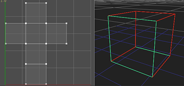
Only this was a human sculpt and not a cube, but the same logic applied. The Aim of UVs are to provide a base for 2D texture maps to be applied to. The UVs need to abide by a few rules to ensure adequate textures.
In order to unwrap the mesh I placed a series of seams (cuts) along certain edges which would allow the mesh to unwrap in a specific way allowing for a 2D map to be projected upon it.
Seams can appear in textures especially after baking all the required map, therefore ensuring seams are kept to a minimum where possible. Next, i needed to layout the UV shells while retaining texel density which is vital as texture maps would at different resolutions on different shells if they have differing relative scale. Therefore, to keep the shells consistent in size while able to facilitate high res textures I used a UDIM layout. UDIMS provide virtually an unlimited texturing space across an array of tiles which are separate from one another. I placed the head shells in tile, 0,0: Arms: 0,1, legs: 0,2, Torso:0,3 etc.
The UVs took about 1 hour to complete from scratch

Once satisfied with the UVs I could begin reprojections in Zbrush. This would allow the high poly details from the original sculpt to be enforced upon the retopoligised mesh. Reprojections don’t always go as planned but if the retopo is adequate usually everything goes as planned, occasionally holes can form in areas (usually around the ears). If something like this occurs you can only go back to retopo, as fixing holes in zbrush is simple, it would compromise the mesh’s topology and UVs making it useless for what we needed it for, this is because in order to fill holes the mesh needs to be dynameshed which is a very useful tool while sculpting to keep things clean. However for every time its used the mesh’s topology is completely redone to what the algorithm is set for.

Once the reprojections were completed I now had 8 different SubD levels, Level 1 being the import resolution which was the original maya retopo I made. the high res levels would facilitate for secondary and tertiary details. However, before moving onto posing and making finer mid/high frequencies details such as pores and imperfections. I needed to make sure the UVs were updated with the reprojections. This is because when reprojecting for the first time the mesh will be morphed to the shape of the sculpt which can be quite a dramatic shift for the vertices, this repositioning of vertices will cause the UVs to be outdates as the vertices in the UV shells no longer line up with those of the reprojected mesh. Therefore, i exported the mesh back to maya at SubD Level 1 and updated them, the shells were slightly different shapes due to the first reprojections as thats where the most change happens.
A consequence of not fixing this could result in stretched textures.

Back into Zbrush i reprojected the base mesh for a second time, this time there was less change in the overall shape of the mesh as i went up each Sub D level. Once all 8 levels were back i could begin the detailing stage. This would take up to several days to ensure a quality end result.
Detailing the base mesh was a long job but would pay off massively as it meant i could export a displacement map and cavity map directly from Zbrush. the Displacement map is a 32 bit exr file which is a hugely dense map which is a map responsible for driving the high res details of the mesh in the Maya render.


Like i said earlier Zbrush can handle very high poly counts, however, this would cripple any non-sculpting application such as maya. A displacement map is essentially a 2D visualisation of these high res details handled by the render engine instead of having to be a 3D mesh live in the viewport which would cripple the program as Maya isn’t built for that. Applying the displacement map can sometimes become a bit of trial and error.
This is because the displacement map has 3 main values, a max in, max out and neutral value. For example, Black is the maximum in Value and White is the Max out Value. however, Maya doesn’t always interpret the data the same way as Zbrush’s export therefore these 3 values may need to be offset in order for Maya’s interpretation to match Zbrush’s.
if the interpretation doesn’t match then the rendered result could look puffy or collapsed depending on what way its offset the most, if perfectly balanced (as all things should be) then the result in both programs should match.
Another difference between Maya an Zbrush interpretations is the Camera, therefore the model in the Maya viewport will look different to how it does in the Zbrush viewport as their Focal lengths are not the same to one another by default. these are complications that can be handled later down the pipeline.
The Cavity map is another map exported from zbrush which will act as a supplementary map when texturing the model later on.
I also posed the retopoed base mesh in Zbrush using its Zsphere tools, this helped make it a slightly more life like pose which wasn’t 100% symmetrical, I didn’t do this earlier as it would have meant doing both sides of the base mesh during the retopo stage.
Now the basemesh was ready for texturing I could move onto modelling the rest of the character.

Modelling/Texturing the armour: Week 3/4
I used a program called Marvellous Designer (MD) which is a specialised tool for clothes simulation. This allowed me to place real world attributes such as a gravity and atmospheric pressure to render a realistic model with wrinkles. To make the shape of the glove I used MD to create a shape which would act as a garment. The MD simulation however neglects the topology in order for it to be simulated efficiently. Next I could export the garment mesh from MD into Maya, an issue which can occur between different 3D application is the scale of the mesh being changed, exporting at the wrong scale such as cm instead of mm would result in a inconsistent scale across different applications which could be the source of many problems down the line. Another attribute that isn’t always correct is the Z and Y axis being flipped which offsets the orientation of the mesh on export. Therefore ensuring these attributes matched up would keep the mesh in a consistent scale and orientation across each program.

Once the garment was exported to Maya, I was able to begin retopo using the Quad draw tool in the same why I did for the base mesh. Once the retopo I worked on the UVs which would be updated later. Next I began to model the armour on the forearm, I began the armour modelling in Maya by using the polygonal tools to create a low poly shape which will later be detailed and refined in Zbrush. To make the low poly shapes I simply began with a single normal and extruded out from there applying edge loops and manipulating individual vertices as I went along. Carrying out these basic functions allowed me to form the basic low poly shapes which would make up the armour.


A particularly challenging shape was a string that would wrap around the edges of the armour to act as the connection where the leather materials meets the metal support around the edge to add sturdiness to the armour. This is a legitimate method that was used to keep armour robust even with relatively weak materials such as leather the armour would still provide a tough interface to defend against enemy strikes, while still being light to where and cheap to manufacture.
To render this effect, I created a long helix, next I made a helix which would act as the string, then made an extruded cylinder which would act as the frame. In order for the Helix to be wrapped around I needed a path for it to follow, this would speed the workflow up considerably compared to manually manipulating the helix and would provide better results. To create a path, I selected an edge loop of the mesh and converted to a Spline which would act as the path for the mesh. Next, I opened the animation tab for Maya; with the Helix and Spline selected I could now apply the helix to the path, however, this required some trial and error with the base orientation and the controlling attribute for its flow.
due to it being a Helix I used the “object up” as the controlling point for its flow. What made this especially challenging to get right result was the path was influenced in all 3 dimensions X,Y and Z, This makes it a lot harder to get a helix to co-operate in a specific way compared to a flat path which only relied on 2 dimensions. Eventually though I got the flow to work in a way that was satisfactory. Next I needed to create a lattice structure which would essentially be a cage that would have its own subdivisions to drive the mesh around the spline. The higher res the cage the closer the helix would conform to the shape of the spline.
The helix was now being influenced by the spline, however I couldn’t do any further manipulations without it undoing its influence with the spline. In order to fix this i deleted the history of the helix shape which would allow the mesh to remain fixed to its current state without having to look back in the node tree of previous actions. This allowed me to treat the conformed helix as if it was any other shape. It also separated the spline from the mesh which allowed me to keep it for reuse later on, or delete it.
Once the low poly was completed I got to work on the UVs which would allow me to texture the model. I would next layout the UVs on an array of UDIMs which keeps the meshes organised throughout the remaining of the modelling stages. Next I imported the meshes into Zbrush, where I increased their SubD levels to allow for a series of details to be made. I began with SubD levels pushing a few hundred thousand to sculpt in basic low frequency details such as large wrinkles in leather, next I increase it to mid frequency details going to about a couple of million which would facilitate for details such as Cracks, smaller wrinkles and other imperfections. As I increased the SubD level further the higher frequency I could go, eventually I adding a high res leather texture to create the micro details and properties featured on leather.

The lower frequency have more influence on the overall shape and silhouette of the mesh whereas high frequency details are really just additional details to contribute towards the texture maps. To make the details I used a series of brushes, the brushes have variables which allow for the brush to be edited so it could be used for very specific a very specific purpose. Such as Size, Intensity, Focal shift, Flow and Alpha. The alpha determined the texture of the brush, therefore applying a different alpha completely changed the look of the brush. Whereas Intensity, Focal shift and Size are variable which would be adjusted while using the alpha to ensure a satisfactory result.
Zbrush is comprised of hundreds of brushes, however, most the time people dont really work with more than 10. Zbrush has about half a dozen core brushes which serve a use in a lot of situations, clay build up is great for building up volume, mask brush, transpose brush, standard brush etc. There’s also plenty of brush’s that are more specialised for specific tasks.
For more organic shapes I started off in Zbrush, to later be retopoed in Maya as this was simply a lot faster than using the basic polygonal tools to create something that’s meant to be organic.

On the glove there was a diamond padding texture in my research which I wanted to replicate, in order to do this successfully I needed I used the mask brush to manually create a diamond tile effect on the glove, next I inverted the mask so instead of the diamonds being masked out it was the lines in between them. Then I applied the clay build up and Inflate brush to add volume to the padding, starting at a relatively high poly count of a few hundred thousand. Once the basic low frequencies had been sculpted in , I increased the poly count to add in Mid frequency details, I also used the pinch brush to create a seam effect between each of the padded diamonds. Quite self explanatory, the pinch brush takes two points and brings them closer towards one another. In the lower frequency details I applied a stitch brush to the seams. There’s a reason why I added this in 3D instead of doing it via a normal map in the texturing stage, this is because in the texturing process involves baking a set of pre-determined maps. Baking is basically when the low poly and high poly mesh is processed in order to construct different channels of information which can be exploited during the texturing stage.

Substance Painter (SP) supports curvature maps, this maps processes the curvature of the mesh to create a grey scale visualisation of the mesh’s surface, essentially where there’s a shift in a dimensional bias, a circle has a constant curve so this would be one colour, whereas a beveled edge would had a shift in colour compared to the flat faces adjacent to it. This is something I plant to exploit when baking out the high poly as I want the stitches to be their own gold texture compared to the fabric of the diamond padding. If i were to paint the stitches gold I would need to manually paint over each stitch in SP this would take time and would need to be done EVERY TIME I readjusted the mesh or wanted the same effect on a different mesh. Therefore, plugging the baked curvature map would act as a procedural approach in which no matter where the stitches are they will always be accounted for via the curvature map making them all gold with just a click of a button with all kinds of different variations of layout. While this method was very effective and took some thinking in advanced prior to texturing to pull off, it wasn’t perfect, as the curvature map also accounted for other curves in the mesh causing the gold to appear in other areas, therefore I did two things to overcome this hurdle, The first was another procedural take on the issue through adding a basic level adjustment where I could use the histogram to narrow the overall range of the curvature map to a specific range, this reduced the amount of gold overflow considerably, but didn’t quite remove everything. Therefore, the second course of action was a more manual approach simply by applying a mask where I would simply paint out any unwanted gold areas.

Substance Painter also handles a rang of other maps which I utilised throughout the texturing stages: Albedo, ambient occlusion, world space normals, roughness, metallic, normal, ID, thickness, Emissions and Curvature. All these maps serve a specific use, I used most of these to create the textures, some were turned off to reduce bake times and overall strain on the graphics card and memory.

Week 4/5
Texturing Skin:
For the base mesh I used Mari as my main tool to texture the skin, Mari and Substance painter are heavily used tools in the industry. I decided to use Mari for the skin as it handles organic forms a lot better than Substance painter and also creates maps which are more beneficial for skin rendering. Furthermore it also accepts displacement maps and allows for UDIMs to be painted over which would be make texturing a lot easier in Mari compared to SP for the skin.
The Skin texturing required several maps: Albedo, roughness, specular, bump, normal, displacement, SSS and Cavity


the Albedo map would hold colour information necessary, not taking into account shadows and reflections, simply just the pigmentation of the skin. Therefore its not as easy as just projecting a photograph onto it, the information needs to be filtered out. The roughness and specularity are both grey scale maps which I used to add shine to the skin where needed, for roughness black means 0% rough and white = 100% rough (no reflected light). Specularity is flipped and allows for concentrations shine across areas of the skin.


Bump and Normal maps were used to illustrate a sense of depth via a 2D visualisation. I actually made the normal map in Substance Painter which i later exported to Mari to save time re-baking it. The normal map is an RGB map which creates the illusion of depth and can be useful for intense skin details such as lip wrinkles. This map doesn’t effect the silhouette like a displacement map but is sufficient in showing depth in these mid frequency details.
The Bump map is grey scale which is dual channel instead of 3 channeled RGB like the normal. the difference with a bump map the depth is just in or out, black or white. This makes it effective at getting pores and other high frequency details on the skin.
The displacement map I used was directly from Zbrush, unlike a bump and normal map this adds actual geometry to the mesh to simulate depth, therefore this has an effect on the silhouette. This map takes far more time to process in the render, therefore in games other methods such as tessellation are preferred, in VFX however, which is the context of what i’m using it for, displacements are a very common method in films as it keeps the view port model low poly which is very important for Riggers and Animators further down the line, therefore the displacement is almost like a cache of the high poly information which is enforced onto the model during the rendering stages and instead of being reliant on geo, its reliant on UVs.

The Cavity map is a supplementary map I use for texturing the skin. Exported from the Zbrush high poly base mesh I could layer this over the albedo map via an Overlay adjustment layer which would allow for some pore details to make it into the Albedo. This sort of contradicts the functions of an Albedo having to be the flat colour value’s as the darker areas of pours are mostly shadows. However, having this map on top of the albedo helps with getting more details out in the final render as the normal/bump map usually look a bit flat on their own without the help of some exaggeration in the Albedo.

SSS stands for Sub Surface Scattering. This map played a large role in getting the skin to look right. Skin isn’t completely opaque and light needs to travel through the skin, this doesn’t apply everywhere on the face but applies in places around the mouth, nose, eyes and ears. The SSS map is just a grey scale map which essentially works as a mask, White = true and black = false. Most the work takes place in the shader setup prior rendering rather than actually making the SSS map, the extra worked certainly paid off in my opinion as it added life to the skin which helped render a more convincing piece.
Once I was happy with the texture work I exported each of these maps in 4k at 8 bit except for the displacement map which was a 32 bit 8K export. I would most likely come back to Mari to make changes to the textures later on as they would automatically plug into the render on Export once the shader is setup.
Shader Setup / Render Engine

Despite being far from done with the character itself, the shader setup is one of the final stages prior to rendering. This is mostly processed by the computer and not the user which is why its a separate stage from the texturing. However, the setup still took me about half a week to setup and get a satisfactory end result in the Arnold render engine.
Arnold is built into Maya and is one of the better known render engines, its been used for many productions and is a CPU based engine. personally I would have preferred to use a GPU based engine such as Redshift, but Arnold was the better choice for the long run. Arnold does have a beta GPU rendering version, however is still too unstable and slow for me to trust fully with this project.
AiStandard Surface is one of Arnold’s primary materials which offers a huge range of channels and is very versatile. This will allow me to plug all my maps via the shader.

Setting up the sub surface scattering was the main challenge with the skin shader as it required several additional nodes to be added to the graph including a hue shift. This is because when light is passed through the skin it looks more red and not white. The SSS map would be accompanied by the Albedo map as the SSS determined where Scattering occurs it didn’t control the colour, therefore plugging the Albedo to SSS helped with getting the scattering to look accurate.
Another challenge with SSS is I found it difficult to know if it was too high or not, therefore i turned to sending it some guys I knew in the industry for feedback, they advised I lowered it, soon the skin began to look a lot more realistic, turned out SSS can be quite difficult to judge and can be easy to exaggerate. This was something i’ve had little experience with so reaching out to others for feedback really helped me obtain better results.
Looking at the skin it seemed a little too warm, therefore I went back to Mari and added a basic “grading” adjustment layer where I could non-destructively edit the tone of the skin. Because the shader was now setup I could simply export it over the previous export and everything would update in the shader.
Eye Modelling/Shader Setup

Eye’s are something ive struggled with in the past, therefore this time I spent a lot more time on the model. without proper research most would assume the eyes are just a sphere, but its actually more oval shaped and has a slight extrusion where the iris begins. Furthermore, the eye also has refraction occurring around the iris. The pupil is also a hole not a spot so that’s another thing I carefully took into account when modelling the eye.

When modelling the eye I divided it into two separate models, The inner layer with the iris and pupil, and the outer layer with the extruded cornea. After making the UVs I found some open source eye scans. This simply was needed as I couldn’t really do it any other way. I then converted the scans into simply two maps, an albedo and a bump map. no other map was needed as the shader could easily handle the roughness and spec on its own.
The cornea needed to be transparent and needed refraction to work. This could be done procedurally, the UVs were layered out in a such a way where it was possible to make a black circle to simulate transparency. This was done via a ramp which would simple be a black to white gradient which would match the area of the UVs where the eye needed to be transparent. This ramp could easily be manipulated meaning nothing was final and could be change in an instant, therefore this procedural node approach was best for an efficient execution. Next I needed to setup the refraction of the iris. This is the offset of light rays as they enter the medium of the cornea. This is what makes the iris look like its on the cornea from the side view, its like looking into a swimming pool, the same occurs here. To render this effect the Ai Standard Shader featured an IOR (index of refraction) variable which took some trial and error to get just right. too low the iris looked flat, too high the pupil in the center begins to refract causing it to look offset from the center.
The Albedo for the eye was a little two intense causing it to look bloodshot, however, due to the scan being a 32 bit file it was easy to adjust this without distorting the map as there was plenty of information to work with. Another issue I encountered was with the bump map overlaying the cornea which resulted in a weird texture to form on the eyes. To fix this I opened up Photoshop and neutralised the values which were slightly too far over the cornea.
Because the pupil was an actual hole in the mesh it was also very easy to adjust in size. Furthermore due to the refraction there was even red shift taking place in the eyes under intense lights, this is sometimes the outcome of a flash camera causing the eyes to look red in the center.
Once I was happy with the shader networks I could now reuse these in future projects. All that would be different is the maps being imported to them.
Week 5/6
Substance Painter
Other than the skin all the remaining texturing work was done in Substance Painter. Prior to importing to painter i made final adjustments to the mesh I wanted to import. This is for several reasons. Working with UDIMs in SP isn’t the best of things as its only recently began to offer UDIM support as it’s used more by games companies, however every year more VFX houses are using Substance applications as they’re getting ahead of competing brands such as Quixel and Mari. Each UDIM must have no overlapping UV’s anything like this will fail to import. Another common issue with painter is it flips the normals occasionally on import, freezing the transformations prior export usually fixes this error.
Prior to exporting I also created an ID map to associate with individual objects. This will help prevent errors from occurring when baking the textures. This is because the objects in the same UDIM which are overlapping one another could cause projection errors during the bake, therefore an ID map is a way of which Substance can keep each mesh separate when baking out to prevent artefacts and errors from occurring.
When baking each map I selected the high poly export from zbrush I wanted to be applied to the low poly using World space projections instead of UV based. this meant it would look at the 3D positioning of the high res bake not its UVs, both have their uses. However, the high res UVs wouldn’t be compatible, however, their world space is as when exporting meshes to and from different applications I keep them in the same scale, orientation and location within the viewport. Therefore this baking method is the best option here. For the baking quality I set it to 8K which is high but will prevent aliasing without the need for anti-aliasing. Setting the ‘out’ value to .81. This determines how far Substance looks beyond the surface of the normals to project onto the mesh.
The high and mid frequency details I did in Zbrush really benefitted the overall look of the texture work. This was due to all this information being placed into maps via the bake. The Curvature, AO and height maps really benefited from this. I also created some of my own materials which worked procedurally making them reusable for any other models I wished to use them on in the future. The procedural features of Substance made the texturing process very efficient, however, procedurals weren’t enough on their own. Therefore a lot of the texture work was done manually allowing them to tell a story through their imperfections and markings. For example two metals parts which joined together would have a lot of wearing in the areas where they both came into contact. Also if the environment surrounding had water or other substances, there may be some corrosion/rusting appearing on the metal. When doing armour, often their is more damage on the left hand side as most opponents would be right handed. These are small things which I learnt a lot from by applying it to my texture work.
Now all the maps are baked I could begin texturing each of the models. The file size was a problem as for each time I baked or added more layers to the stack the file grew in size. Some files pushed beyond 25GB each. Luckily on the export all this information would compiled down into 4 different 8 Bit 4K png files.
Due to the large range assets I was working with, with there being over several hundred individual models in total all with their own textures, It was important to establish a file structure early on. Therefore I created a single directory which would store all the armour texture maps. Maya will have to rely on these file stored externally. If the path was to be changed then Maya would need to be updated.
All the textures were imported via a file node which plugged into the ai_Standard shader in Arnold.

Lighting


Lighting is one of the final stages, and is absolutely vital in assuring the final render looks some what good. Because no matter how well done all the modelling and texturing is, lighting is always deciding factor in how the end product looks.
The lighting has to be setup from scratch within the maya view port. With no lights , then the render engine wouldn’t have any information to work with. I had 3 options to light my scene. The first was to setup a basic sky dome, this would have been the fasted but the lighting would look very flat and lack contrast and depth to the character.
The next option would be similar however instead it would be via a HDRI image. this is a 360 image that can wrap around the sky dome to create a more specific lighting situation for the character.
The third option involved manually placing a series of area lights around the scene, this would take the longest however, would give me the most control over the lighting as each light could be individually manipulated. This allowed me to create contrast and depth. I was also able to change the attributes of each light such as intensity, exposure, colour etc which provided a lot more control in comparison to the previous two options
I setup the lights, making them a slightly cream tone in colour. They were white by default however this made a it look quite stale and flat. This very slight adjustment made a nice difference.
Rendering


Rendering in Arnold was the final required stage. With the lighting setup a lot of the work was now done. The rendering process however now needed to be optimised. I first increased the resolution and DPI of the render. This dramatically increased the details in the render. Next I went into the samples which essentially is a measurement for how much information is recorded by the engine.
If one of these samples were too low, then noise would appear in the render. There’re different situations where noise occurs which can help the user recognise where more samples are needed.
Camera (AA) Anti-Aliasing, is of most importance in assuring clarity within the render.


As these were test renders I kept the samples relatively low to reduce rendering times so I could quickly view other changes I made within the scene. For the Final renders these samples would be increased.
Next I wanted to setup AOVs which are Arbitrary Output Variables.

These are layer’s of filtered out data from the render itself which can help in post processing. They aren’t essential for the render but can help further down the pipeline.
For final optimisations, I adjusted the low light threshold. This value is responsible for deciding how sensitive Arnold is to light in the scene. The lower the threshold the more light sensitive to light. By default this was set to .001 which pretty much the lowest value. While this benefited the quality, the difference between .001 and .06 was barely noticeable, however render times were a lot faster at .06 in comparison to .001. going any higher than .06 made a more noticeable difference. By .1 the render times dropped from 8 hours to 20 minutes, however this was a more considerable drop in the quality
Low light works with a logarithmic growth system. The render times seemed to divide in half every time I increased it. however, eventually the render times begin to level out as the difference in half becomes smaller and low light threshold no longer becomes the limiting factor.

Xgen:

Xgen is the groom tool built into Maya which is heavily used within the VFX and Games industry to generate hair for characters. It also supports fur through an interactive groom system.
Xgen relies on splines which is an interpretation of edge which is responsible for driving the hair system. The hair is stored externally from Maya in a series of files. This is defined when setting up the project and when creating a new description of hair. The hair description MUST reside within a collection. A collection is a group of descriptions and allows for a hierarchy to be setup in advance. The Splines are manually shaped by the user. The hair attributes can be manipulated through a range of sliders such as density, width and length in relation to the spline layout. The less splines the less specific the end result will look making it look artificial.
The hair can also be influenced by a series of maps, there’s virtually an unlimited range of maps that can be made using Xgen but there are several core maps that are often used to ensure a satisfactory end result. A density map is a Black/White map which controls where hair is to appear and where it shouldn’t. The white value represents where the hair should appear.
The Hair Braid was especially challenging as It required getting guides to flow in a certain way. Therefore I needed to create a set of guides that were shaped in this very specific way. To make the braid I first created a curve which would visualise the flow of the braid.


